

Operation Process and Working Principle of Denitrification Urea Material Handling System
Denitrification urea material handling systems are critical components in industrial facilities that employ selective catalytic reduction (SCR) technology for flue gas treatment. These systems are designed to transport urea solution, a key reagent used in the SCR process, from storage tanks to the injection point in the boiler or flue gas duct. The efficient operation of such systems is essential for maintaining optimal NOx reduction efficiency and ensuring the smooth functioning of the overall flue gas treatment system.
System Overview and Key Components
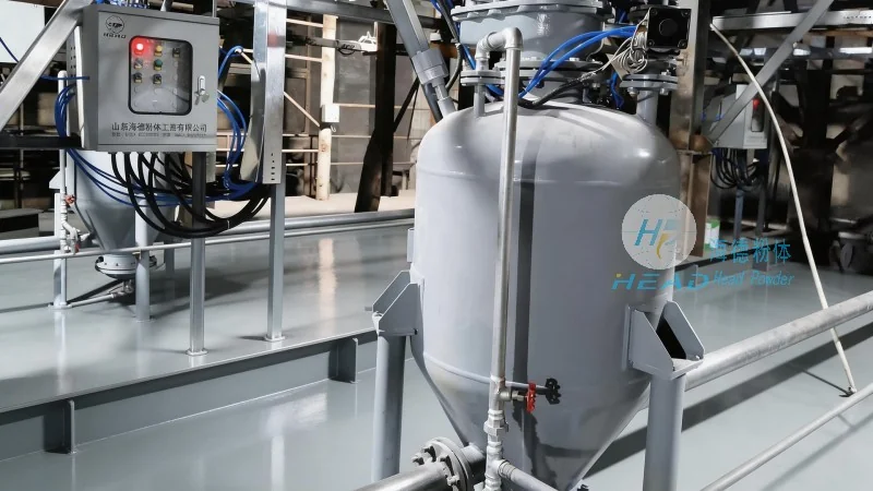
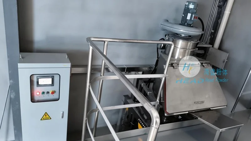
The denitrification urea material handling system typically consists of several interconnected components, each playing a vital role in the safe and reliable delivery of urea solution. The primary components include storage tanks, pumps, pipelines, valves, and control systems. The storage tanks are used to hold the urea solution under appropriate pressure and temperature conditions to prevent degradation or crystallization. Pumps are responsible for transferring the urea solution from the storage tanks to the injection system, ensuring consistent flow rates and pressure levels. The pipeline network connects the storage tanks to the injection point, with valves controlling the flow direction and regulating the flow rate. Control systems monitor and adjust the operation of the pumps and valves based on real-time parameters such as pressure, flow rate, and temperature, ensuring the system operates within safe and efficient parameters.
Working Principle of the Material Handling Process
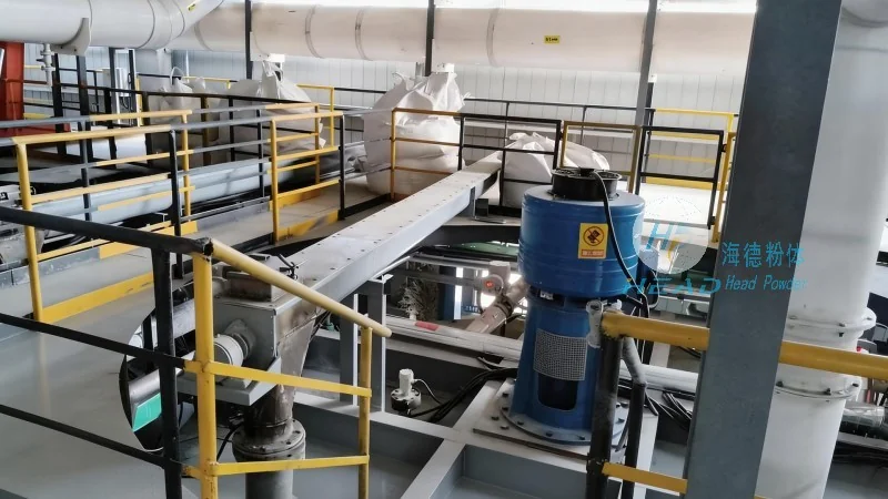
The operation of the denitrification urea material handling system involves several sequential steps that ensure the urea solution is delivered to the injection point in the correct quantity and at the appropriate time. The process begins with the preparation of the urea solution in the storage tanks. The solution is typically made by dissolving urea in water to achieve the desired concentration, which is critical for the effectiveness of the SCR process. Once prepared, the solution is stored in the tanks under pressure to maintain its fluidity and prevent evaporation or contamination. The next step involves the activation of the system, where the control system initiates the pump operation. The pumps then draw the urea solution from the storage tanks and pump it through the pipelines to the injection point. The flow rate and pressure are carefully controlled to match the requirements of the SCR system, ensuring that the urea solution is delivered at the correct rate to react with the NOx in the flue gas. The injection point is typically located in the boiler or flue gas duct, where the urea solution is mixed with the flue gas and reacts with the catalyst to reduce NOx emissions. The system continuously monitors the flow rate and pressure to maintain consistent operation and adjusts the pump speed or valve position as needed to compensate for changes in the flue gas flow or temperature.
Operation Process Flow
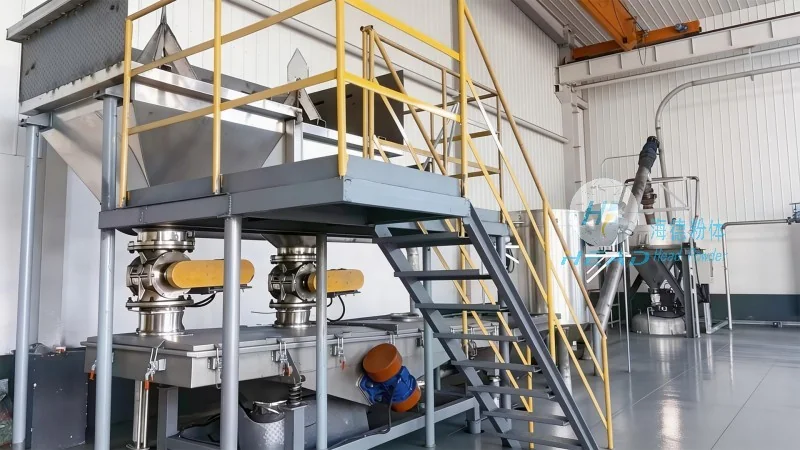
The operation process of the denitrification urea material handling system follows a systematic flow that ensures the smooth and efficient delivery of urea solution. The process starts with the preparation of the urea solution, which involves dissolving urea in water and adjusting the concentration to the required level. The prepared solution is then stored in the storage tanks, where it is maintained under pressure to prevent degradation. The system is then activated by the control system, which initiates the pump operation. The pumps draw the urea solution from the storage tanks and pump it through the pipelines to the injection point. The flow rate and pressure are controlled by the control system to ensure consistent delivery. The injection point is located in the flue gas duct, where the urea solution is mixed with the flue gas and reacts with the catalyst to reduce NOx emissions. The system continuously monitors the flow rate and pressure to maintain optimal operation and adjusts the pump speed or valve position as needed to compensate for changes in the flue gas flow or temperature. The entire process is automated and controlled by the system's control panel, which provides real-time monitoring and adjustment capabilities to ensure the system operates within safe and efficient parameters.