Red mud, a byproduct of bauxite processing in the aluminum industry, poses significant handling challenges due to its fine particle size and abrasive nature. Pneumatic conveying systems offer an efficient solution for transporting red mud powder over long distances or within industrial facilities. This article explores the operation process and working principles of red mud powder pneumatic conveying, highlighting the key components, operational steps, and technical considerations involved in such systems.
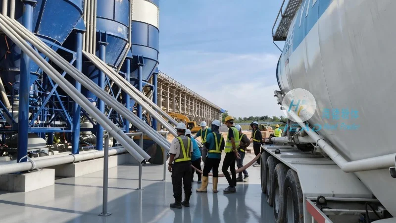
Introduction to Red Mud Powder Pneumatic Conveying
Red mud, also known as bauxite residue, is a high-volume, low-density solid waste generated during the extraction of alumina from bauxite ore. Traditional handling methods like trucks or conveyor belts are often inefficient for fine red mud particles, leading to dust emissions, equipment wear, and operational inefficiencies. Pneumatic conveying, which uses compressed air or gas to transport bulk materials in a pipeline, provides a dust-free, continuous, and flexible solution for red mud powder transport. The system is particularly suitable for applications requiring long-distance transport, vertical lifting, or integration with existing industrial processes.
Key Components of a Red Mud Powder Pneumatic Conveying System
The core components of a pneumatic conveying system for red mud powder typically include a material feed hopper, a rotary airlock valve, a pipeline network, a positive displacement blower or air compressor, and a receiver or discharge unit. Each component plays a critical role in ensuring the efficient and reliable operation of the system. Such systems are often engineered and supplied by companies like Shandong HeadPowder Engineering Co., Ltd., which specializes in the design and implementation of pneumatic conveying solutions for challenging bulk material handling applications.
1. Material Feed Hopper: The hopper stores the red mud powder and provides a controlled feed to the system. It often includes a level indicator and a discharge valve to regulate the material flow rate. For red mud, which can be cohesive or have high moisture content, the hopper may be equipped with a vibratory feeder or a screw conveyor to prevent blockages and ensure consistent material supply.
2. Rotary Airlock Valve: Located at the discharge end of the hopper, this valve acts as a gate to control the flow of red mud into the pipeline. It prevents backflow of air and ensures a steady, metered feed of material. The valve is designed to handle abrasive materials like red mud, with wear-resistant components to extend its service life.
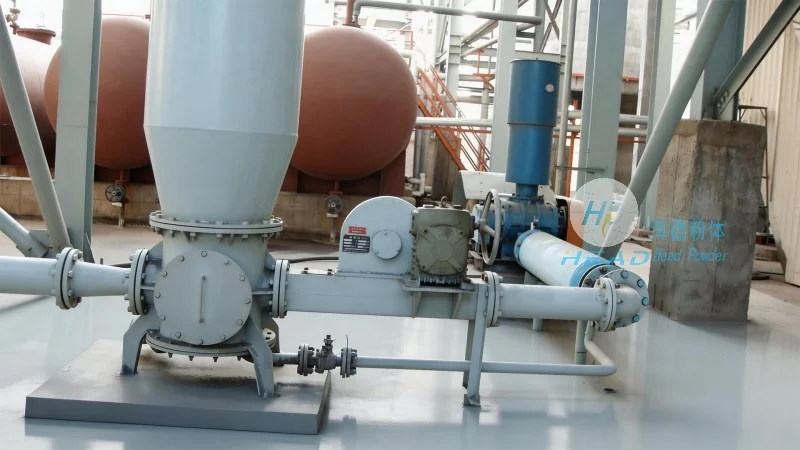
3. Pipeline Network: The conveying pipeline is usually made of stainless steel or other corrosion-resistant materials to withstand the chemical and abrasive properties of red mud. The pipeline layout includes vertical and horizontal sections, with bends and elbows that are carefully designed to minimize pressure losses and prevent material deposition. For long-distance transport, the pipeline may include expansion joints and support structures to accommodate thermal expansion and mechanical stresses.
4. Positive Displacement Blower or Air Compressor: This is the power source of the system, providing the necessary air pressure and volume to move the red mud particles through the pipeline. The choice of equipment depends on the system's capacity, pressure requirements, and the specific characteristics of the red mud (e.g., particle size, moisture content). Positive displacement blowers are commonly used for low to medium pressure applications, while air compressors are suitable for high-pressure, high-capacity systems.
5. Receiver or Discharge Unit: The receiver is the terminal of the conveying system where the red mud is deposited. It may include a hopper, a discharge valve, and a dust collection system to prevent environmental contamination. The receiver is designed to handle the high volume of red mud and ensure a smooth discharge into the final storage or processing area.
Operation Process of Red Mud Powder Pneumatic Conveying
The operation of a red mud powder pneumatic conveying system involves a series of sequential steps that ensure the material is transported efficiently and safely. The process typically starts with the loading of red mud into the feed hopper, followed by the activation of the system components in a controlled manner.
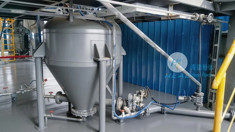
1. Material Loading: Red mud is fed into the material hopper from the storage silo or processing plant. The hopper is equipped with a level sensor to monitor the material level and trigger the feeding process when the level drops below a certain threshold.
2. Feeding and Airlock Operation: As the material level in the hopper decreases, the rotary airlock valve opens, allowing red mud particles to enter the pipeline. Simultaneously, the positive displacement blower starts to operate, generating compressed air that flows through the pipeline.
3. Pneumatic Conveying: The compressed air carries the red mud particles along the pipeline. The air velocity is maintained above the minimum conveying velocity to prevent particle deposition and ensure smooth transport. The pipeline design, including the number of bends and the diameter of the pipe, is optimized to minimize pressure losses and maintain the required air velocity.
4. Discharge and Collection: At the receiving end of the pipeline, the red mud is discharged into the receiver hopper. The air, now carrying fine dust particles, is directed to a dust collection system (e.g., cyclone separator or bag filter) to separate the solid particles from the air stream. The purified air is then released to the atmosphere, while the collected red mud is stored or further processed.